Main menu
Primary application functions are controlled and initiated from the main menu. The main menu is shown along the top edge of the main window .

Where appropriate the main menu will be extended with further functions provided by an active window. For example the menu item File will contain the function Print if some report window is currently active. Likewise, when there is an active report window menu item File→Export will be extended with "→Export→Report..." and while there are active 3D windows (Elements3D, Results3D) the menu View will be extended with 3D-Navigation menu items, and accordingly, the menu File→Export with →Export→Image 3D... and →Export→Scene 3D... with menu Edit extended by →Copy Image 3D.
During some processing steps are executing (e.g. longer operations like calculating the solution or preparing evaluation data) functions of the main menu will be turned off. This will be made visible by greying out the menu characters. While the menu is deactivated it is not possible to use it.
Menu Project
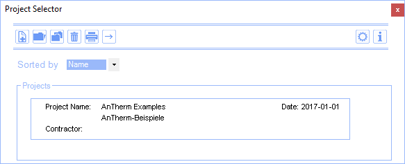
From AnTherm Version 9 on, there is the Menu Project. This menu allows the user to select project files from an existing project (such as "AnTherm-Examples") and open them. Moreover, the user can create new projects and add project files to them. In addition, there are functions such as copy or delete. This menu is supposed to make it easier for users to preserve an overview of all projects and project files. But the traditional way of accessing project files directly via the Menu File is still enabled.
 |
New Project |
 |
Open Project |
 |
Copy |
 |
Delete |
 |
|
 |
Forward (works only if you have already opened a project) |
 |
Settings |
 |
About |
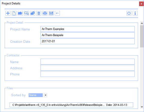
Once you open a project from the Project Selector Window (either by double-clicking the project button or clicking the button once and then clicking the "Open" button), the Project Details Window pops up:
 |
Add Existing File |
 |
New File |
 |
Open Reports Folder |
 |
Save |
 |
Back |
Menu File
 Program
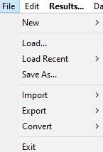
functions put collectively into the menu File are used for file control.
Program
functions put collectively into the menu File are used for file control.
Occasionally there will be further menu items dynamically inserted to this menu,
related to specific
editing windows
or
result/evaluation windows
(if such windows provide additional menu functions).
| New→ |
Creates a new project - see also
project types. Important: prior to creating a new project it is recommended to save the current project's data! |
| New→2D Project |
Create a new project for 2D dimensional input only (imput
of the third dimension will be suppressed) Remark: A 2D project can also be thought as one layer of a " layered 3D project " with the thickness of 1000mm. See also Project types. |
| New→Layered 3D Project |
Create a new project built from series of 2D layers. The
input of the third dimesnion is provided by entering the thickness of each
layer and ordering layers in the
layers list . See also Project types. |
| New→3D Project |
Create a new 3D project. Component's construction will be
composed of series of cubes placed in the 3D space. See also Project types. |
| Load... |
Loading an existent
project file |
| Load Recent→... |
A
project file to open can be chosen from the list of
recently edited project files. Remark: The number of file names shown (and remembered by the program) can be changed in application settings . Remark: The list of recently used project files will be saved to the application settings file between program executions. Remark: If the project file listed does not exist the message will be shown and the cleanup of the list offered. |
| Save... |
Save the currently edited (open) project. Currently set
project file will be overwritten. You will not be warned (no question dialog) before overwriting happens! Remark: This, potentially destructive, behaviour can be defined by application setting " Overwrite project without asking " and " Always Ask To Save Project ". |
| Save as... | Will ask you to provide a file name before project data is saved |
| Import→ | Files created with other applications can be imported into the application and the data will be transformed to a valid new project. |
| Import→Waebru.?BT... | Initiates an import from a WAEBRU component file (i.e. .2BT or .3BT file). |
| Import→aCad DXF... | Initiates an import from specially prepared DXF file . |
| Import→Heat2 DAT... | Initiates an import from a Heat2 text input file . |
| Import→Heat3 DAT... | Initiates an import from a Heat3 text input file . |
| Import→Kobru86 DAT... | Initiates an import from a Kobru86 file . |
| Import→Image Underlay... |
Initiates an
import and
registration of an image underlay/overlay
. Remark: This will register an image for XY-Plane only (typical for 2D- and 3D-Layered Projects). To register three underlay images for the 3 planes of a 3D-Project (XY, YZ, ZX) use the context menu of respective quadrant within the Elements23 window. |
| Export→ | Project data (also including result reports for example) can be "exported" to various file formats for further processing in other applications. |
| Export→Coupling Coeff. Matrix... |
Initiates an
export
of the matrix of coupling coefficients (Leitwertmatrix) to a CSV file
which can be then otherwise processed. Remark: This menu function is only available if there are results (the solution) already created and available. |
| Export→Report... |
Initiates an
export of a result report to some external file
which can then befurther
processed. Remark: This menu function is only available if some report window is active. |
|
Export→Image 2D... Export→Image 3D... |
Allows
saving
of images to a picture file
(PNG,
TIF, JPG, BMP, GIF) and
places the image
onto the clipboard
. Remark: This menu function is only available if some graphical window is active (e.g. Elements3D, Results3D, Elements2D, Elements23) |
| Export→Scene 3D... |
Allows
saving of a 3D scene to a 3D
file
(VRML, IV, OOGL, ...). Remark: This menu function is only available if thre is some 3D window (Elements3D, Results3D) active. |
| Convert→ | Project data can be "converted" to some other project type . |
| Convert→Layered 3D Project |
Initiates the
conversion
of currently edited project data to a new
layered 3D project
. Remark: Not each project can be converted to that project type. See also Project types, conversion variants |
| Convert→3D Project |
Initiates the
conversion
of currently edited project data to a new 3D project (in
a 3D project Z coordinates of elements can be entered directly). See also Project types, conversion variants |
| Convert→2D Project |
Initiates the
conversion
of currently edited project data to a new 2D project. Remark: Only projects homogenous in the third dimension (Z axis direction) can be converted to a 2D project (e.g. layered 3D project containing only one layer, or a 3D project of which all elements share same Z coordinates). See also Project types, conversion variants |
| Convert→Revolve to 3D... |
Initiates the
conversion by revolution (rotation)
of currently edited project data of a 2D project to 3D. See also Project types, conversion variants |
| Print Report... |
Initiates
printing of some report
.
Remark : This menu function is only available if some report window is active. |
| Exit |
Initiates the shutdown of the application. Warning: please save project data prior to exiting the application! |
Menu Edit
 Program
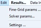
functions placed collectively in the menu Edit are used for adjusting
various processing parameters of the application.
Program
functions placed collectively in the menu Edit are used for adjusting
various processing parameters of the application.
| Fine-Grid params... | Shows the dialog used to adjust fine grid generation settings of the current project. |
| Solver params... | Shows the dialog used to adjust settings of the solver engine in current project. |
| Settings... | Shows the application settings' dialog . |
| Copy Image 2D |
Will copy the image shown in a active window to the
clipboard Remark: This menu function is only available if some 2D graphical window (like Elements 2D) is active. |
| Copy Image 3D |
Will copy the image shown in a active graphics window to
the clipboard
(same a the function "
Copy
image
" of 3D windows). Remark: This menu function is only available if some 3D graphical window (like Elements3D, Results3D) is active. |
Occasionally there will be further menu items dynamically inserted to this menu, related to specific editing windows or result/evaluation windows (if such windows provide additional menu functions).
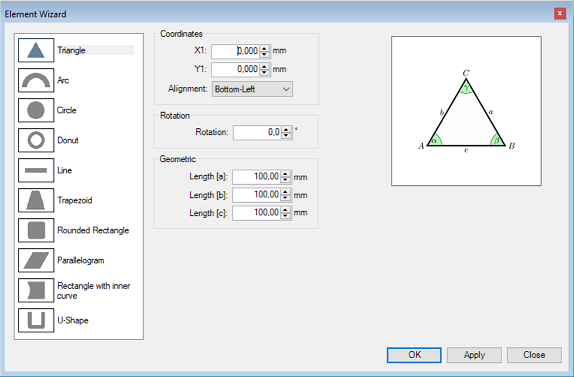
Menu Element-Wizard
With the help of "Element Wizard" you could model geometric figures (triangle, arc, circle ring) in AnTherm.
If you want to rotate the new elements, please do this directly in the Element Wizard, then the rotation will work quickly, otherwise it will take longer.
Menu Results... (or the F5 function key)
The menu Results... initiates calculation of results for the currently processed project. Occasionally you will be asked to save the project data to a project file and to set parameters for fine grid and for the solver engine.
Before the calculation is actually started the application executes series of validation checks on the model construction entered.
The calculation process can be observed in the Solver window . Which calculations are possible depends on actual model data and valid application license features.
After the calculation has successfully completed the application will show the coupling coefficients report (Leitwerte) and will request the input of boundary conditions . Following the later further results reports and evaluations can be performed.
See also: Solver window
Data Input & Entry
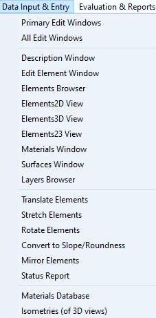 The
submenu Data Input & Entry groups functions used to open
various editing and input windows of
the application. In the normal case most of this windows can be opened in the
processing context from other windows directly too. The menu
Data
Input & Entry
provides in that sense an additional function only.
The
submenu Data Input & Entry groups functions used to open
various editing and input windows of
the application. In the normal case most of this windows can be opened in the
processing context from other windows directly too. The menu
Data
Input & Entry
provides in that sense an additional function only.
| Primary Edit Windows |
Opens primary input windows essential for the current
Ptype of project (Description,
Element selection,
Layers,
Elements 2D,
Elements 3D, etc.) Remark: Which windows are considered essential can be set by user in the application settings for each different project type selectively. |
| All Edit Windows | Opens all input and edit windows of the application |
| Description | Opens the window "Descritpion" |
| Edit Element | Opens the window " Element Editor " |
| Elements Browser | Opens the window " Elements browser " |
| Elements 2D | Opens the window " Elements 2D " |
| Elements 3D | Opens the window " Elements 3D " |
| Elements 2/3D | Opens the window " Elements 2/3D " |
| Materials | Opens the window "Materials" |
| Surfaces | Opens the window "Surfaces" |
| Layers Browser |
Opens the window "
Layers
Browser
" Remark: Not offered for 3D project |
| Translate Elements | Opens the window "Translate" |
| Stretch Elements | Opens the window "Stretch" |
| Rotate Elements | Opens the window "Rotate" |
| Mirror Elements | Opens the window "Mirror" |
| Status Report | Opens the window showing the " Status report " |
| Material Database | Opens the window "Baustoffstammdaten" |
| Isometries (of 3D views) | The list of isometries is shown in the window Isometries. |
Menu Evaluation & Reports
The
submenu Evaluation & Reports groups together functions used
to open various results- and
evaluation windows
of the application. 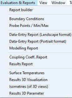
| Report builder | Opens the window " Report Builder " |
| Boundary Conditions | Opens the window " Boundary Conditions " |
| Probe Points / Min/Max | Opens the window " Probe Points / Extreme (min/max) Locations " |
| Data-Entry Report | Opens the window " Data-Entry Report " |
| Modelling Report | Opens the window " Modelling Report " |
| Coupling Coeff. Report | Opens the window " Coupling Coefficients (Leitwert) Report " |
| Psi-Value Determination |
Opens the window "
Psi-Value
Determination
" Remark: This function is available for a 2D project only. |
| Results Report | Opens the window " Results Report " |
| Results 3D Visualisation | Opens the window " Results 3D " |
| Isometries (of 3D views) | The list of isometries is shown in the window Isometries. |
| Results 3D Parameter | The choice list of evaluation parameters is shown in the window Results3D Parameter . |
Menu View→2D Navigation
Menu items of 2D navigation are displayed as sub-items of the menu View if there is a 2D window active (Elements2D, Elements23). Functions of this menu control the movement of the element display within the two dimensional view.
|
Zoom In Zoom Out |
The view can be „scaled“. |
| Fit to window | Adjust the position and scaling in such way, that the whole construction is visible within the window. |
Menu View→3D Navigation
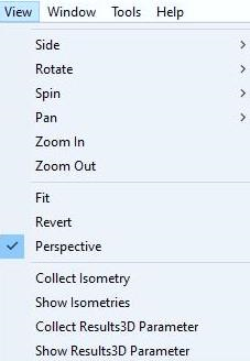 Menu
items of 3D navigation
are displayed as sub-items of the menu View if
there is a 3D window active (Elements3D,
Elements23,
Results3D
).
Functions of this menu control the movement of the camera (observer)
within the three dimensional scene.
Menu
items of 3D navigation
are displayed as sub-items of the menu View if
there is a 3D window active (Elements3D,
Elements23,
Results3D
).
Functions of this menu control the movement of the camera (observer)
within the three dimensional scene.
| Side | Turns the 3D view. The camera is moved to one of side view positions (Front, Bottom, Top etc.) |
| Rotate |
The camera is moved on the surface of a sphere (the
distance to the object's centre does not change). Turns are executed in 30° steps. |
| Spin |
The tilt of the camera is changed. Tilts are executed in 30° steps. |
| Pan | The camera pans. |
| Zoom In/Out |
The camera moves forwards or backwards. With the parallel projection it is equivalent to scaling the view. |
| Fit | The scaling and position of the view is adjusted to fit the whole building construction within the window's view. |
| Revert |
Restore the original standard camera position. X/Y plane parallel to view plane. Z axis point towards the viewer. Y axis points upwards. Scaling adjusted to fit the view. |
| Perspective |
Swithes the 3D display between
perspective projection
and parallel projection. The parallel projection is useful for 2D components or slice views (see also "Side Views" here above). |
| Collect Isometry |
The current position of the 3D display (in
Elements3D,
Elements23 or
Results3D) is added to the
project specific
list of isometries
. The list of isometries can be edited in the window Isometries (each entry can be named for example) or one of listed isometries can be selected from the list and applied to 3D views. |
| Show Isometries | The list of isometries is shown in the window Isometries. |
See also: 3-D Navigation (control panel) , 3D Navigation in 3D windows , Track-Ball Rotation , Results3D window , Elements3D window, Elements23 window, Isometries window
Menu View→Results 3D
Menu items of Results 3D are displayed as sub-items of the menu View (see above) if there is Results3D window active. Functions of this menu control settings (parameters) of the evaluation.
| Collect Isometry |
The current position of the 3D display is added to the
project specific
list of isometries
. The list of isometries can be edited in the window Isometries (each entry can be named for example) or one of listed isometries can be selected from the list and applied to 3D views. |
| Show Isometries | The list of isometries is shown in the window Isometries. |
| Collect Results3D Parameter | Current settings (parameter) of a graphical evaluation in the Results3D window are saved and added to the project specific choice list of evaluation parameters . |
| Show Results3D Parameters | The choice list of evaluation parameters is shown in the window Results3D Parameter . |
See also: Results3D Parameter window , Isometries window , Results3D window , General (control panel) , 3D Navigation (control panel)
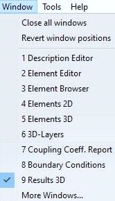
Menu Window
 The
Window menu holds functions used for management of windows. In addition a
list of open windows is pinned at the bottom of the menu and thus allows direct
access to this windows (e.g. activation and bringing the window to front).
The
Window menu holds functions used for management of windows. In addition a
list of open windows is pinned at the bottom of the menu and thus allows direct
access to this windows (e.g. activation and bringing the window to front).
| Close all windows | Closes all application window (except from main application window ). |
| Revert window positions |
Window positions will be reset to its initial positions as
of the very first application start-up. Remark: You must additionally confirm that request before it is executed. See also: Initial template of window positions AnTherm.exe.LayoutPersistence.xml |
| List of window names |
List of all open windows. It is used to activate any of
already open windows. Remark: The list is shown only in the MDI application mode . |
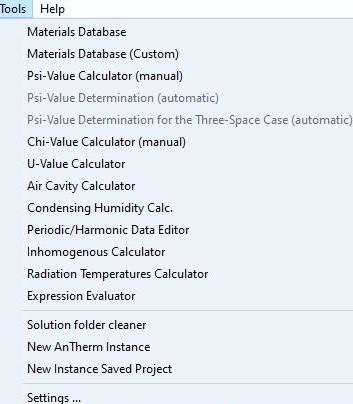
Menu Tools
 The
menu Tools collect various application tools. This additional
function collectively shown in this menu have no direct impact on edited
construction and are used as help for calculations.
The
menu Tools collect various application tools. This additional
function collectively shown in this menu have no direct impact on edited
construction and are used as help for calculations.
| Materials Database | Opens the window " Materials Database " |
| U-Value Calculator | A tiny tool to calculate a U-Value of a layered construction . |
| Psi-Value Calculator (manual) | The tool to calculate a Psi-Value used for rapid calculation of the linear thermal transmittance of arbitrary thermal heat bridge. |
| Psi-Value Calculator (automatic) | The tool to calculate a Psi-Value used for rapid calculation of the linear thermal transmittance of a thermal heat bridge. In contrast to the manual calculator, the data is derived from the current model. |
| Psi-Value Calculator for Three Rooms | The tool to calculate a Psi-Value used for rapid calculation of the linear thermal transmittance of a thermal heat bridge, for models consisting of three rooms. |
| Chi-Value Calculator | The tool to calculate a Chi-Value used for rapid calculation of the point thermal transmittance of a thermal heat bridge. |
| Air Cavity Calculator | A tiny tool to quickly calculate equivalent heat transfer coefficient of small air spaces and cavities based on dimensions of the cavity and heat stream direction. |
| Condensing Humidity Calculator | A tiny tool to calculate condensing humidity (dew point) based on input of surface temperature and space (air) temperature. |
| Periodic / Harmonic Data Editor | Provides the means of creating, editing and managing periodic data required as boundary conditions to transient evaluation (requires TRANSIENT license feature) |
| Expression Evaluator | A tiny pocket calculator able to calculate simple expression (formulas) like 1/25 or Math.Sin(3.14). |
| Inhomogenous Layer Calculator | A tool for the calculation of inhomogenous layers. The result is the attributes of an equivalent homogenous layer. |
| Simulation Folder Cleaner | A tool used to cleanup unneeded simulation folders . |
| New AnTherm Instance |
The second (or next) new instance of AnTherm will start in parallel to the current. Remark: Neither current project data nor application settings are saved! The new instance loads with earlier settings. Remark: This function is available only if the setting "Multiple app-instances allowed" has been activated within application settings . |
| New Instance Saved Project |
After requesting the user to save project data (equivalent to File->Save as...) the second (or next) new
instance of AnTherm will start and load the project data just saved. Remark: Current application settings are not saved! The new instance loads with earlier settings. Remark: This function is available only if the setting "Multiple app-instances allowed" has been activated within application settings . |
| Settings... | Shows the application settings' dialog . |
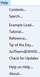
Menu Help
 In
the menu Help you will find links to various help and information
functions of the application.
In
the menu Help you will find links to various help and information
functions of the application.
| Contents... | Shows the help window and the table of contents of the application's help system. |
| Index... | Shows the help window and a searchable index of the application's help system. |
| Search... | Shows the help window and a keyword search window of the application's help system. |
| Example Load... | Using the same function as of File->Load a list of files in the examples folder (created during installation) will be offered. This allows quick access to example files deployed together with the application installation. |
| Tutorial.... | Shows first page of tutorials (cook book) . |
| Reference.... | Shows first page of short reference . |
| Tip of the Day.... | Shows the dialog window "Top of the Day" . |
| Release Notes.... | Shows first page of the change log (history of changes to applications). |
| AnTherm@WWW... |
Shows the AnTherm's web page on internet (requires internet
connection).
Currently the page at the URL http://www.antherm.kornicki.de/ is shown. |
| Check for Updates... |
Checks if there are updates or new version of the
application (requires internet connection). Currently the page at the URL http://www.antherm.kornicki.de/support/CheckForUpdates/ is shown.. |
| Help on Help... | Shows the help window describing the usage of the help system. |
| Info... | Shows the About window of the application (application adn system environment, license, etc.). |
Remark: With the application setting "Help Window shown TopMost" the user can decide if the Help window will be shown topmost to all application windows and automatically minimize with the application (which is the windows default behaviour) or it can be set behind the application window via typical desktop window manager (default application setting).
See also: The main application window, Editing windows (Input windows), Evaluation windows, Dialog windows